Hardware
Description
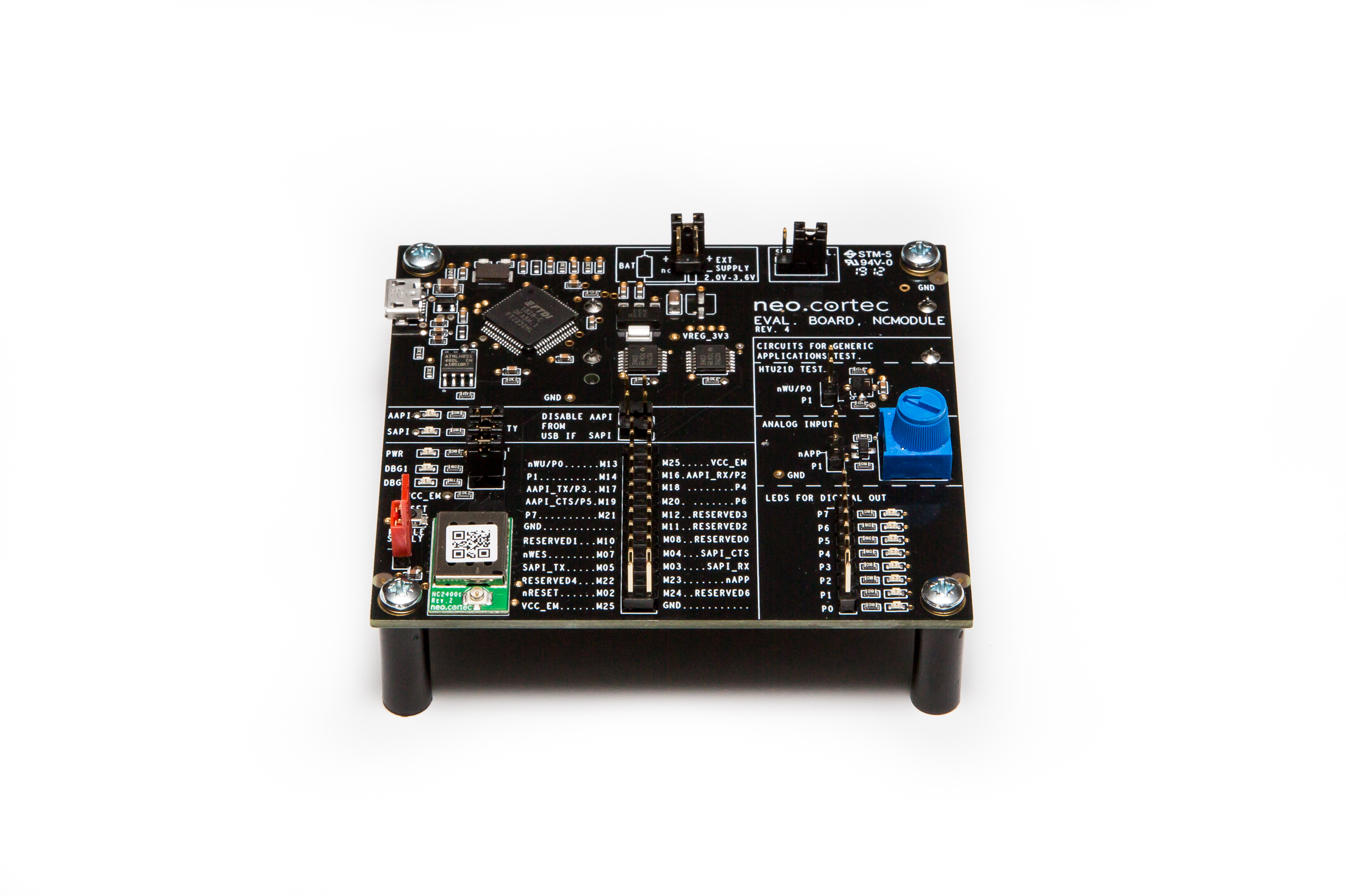
The NeoCortec development board offers you an opportunity to explore the possibilities with NeoMesh right out of the box. Your devices come with a factory configuration, enabling them to function without additional configuration.
Demo Board
Before moving on to the tutorials, explaining the use and capabilities of the NeoMesh network, familiarizing ourselves with the configuration of the demo board is necessary.
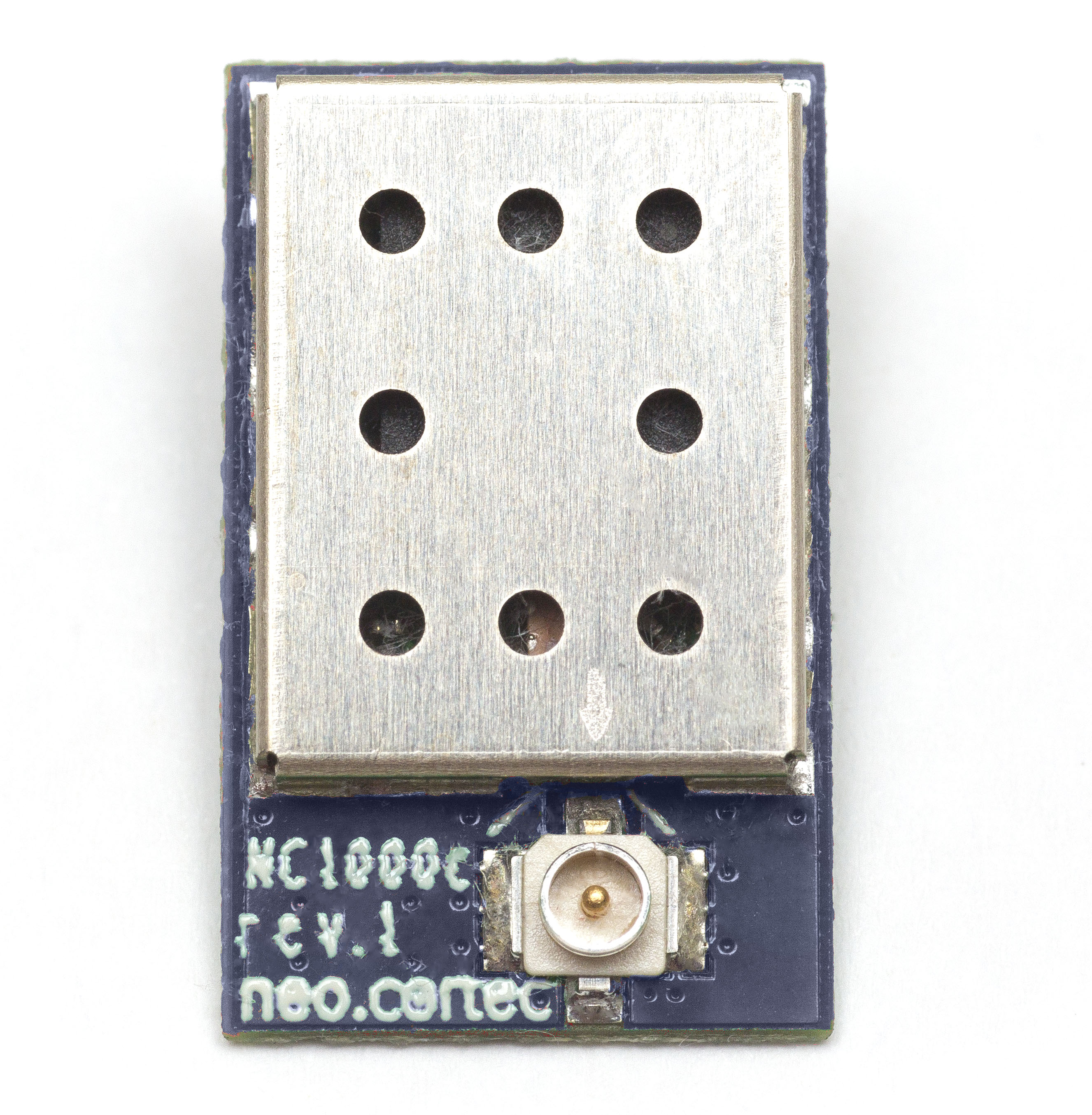
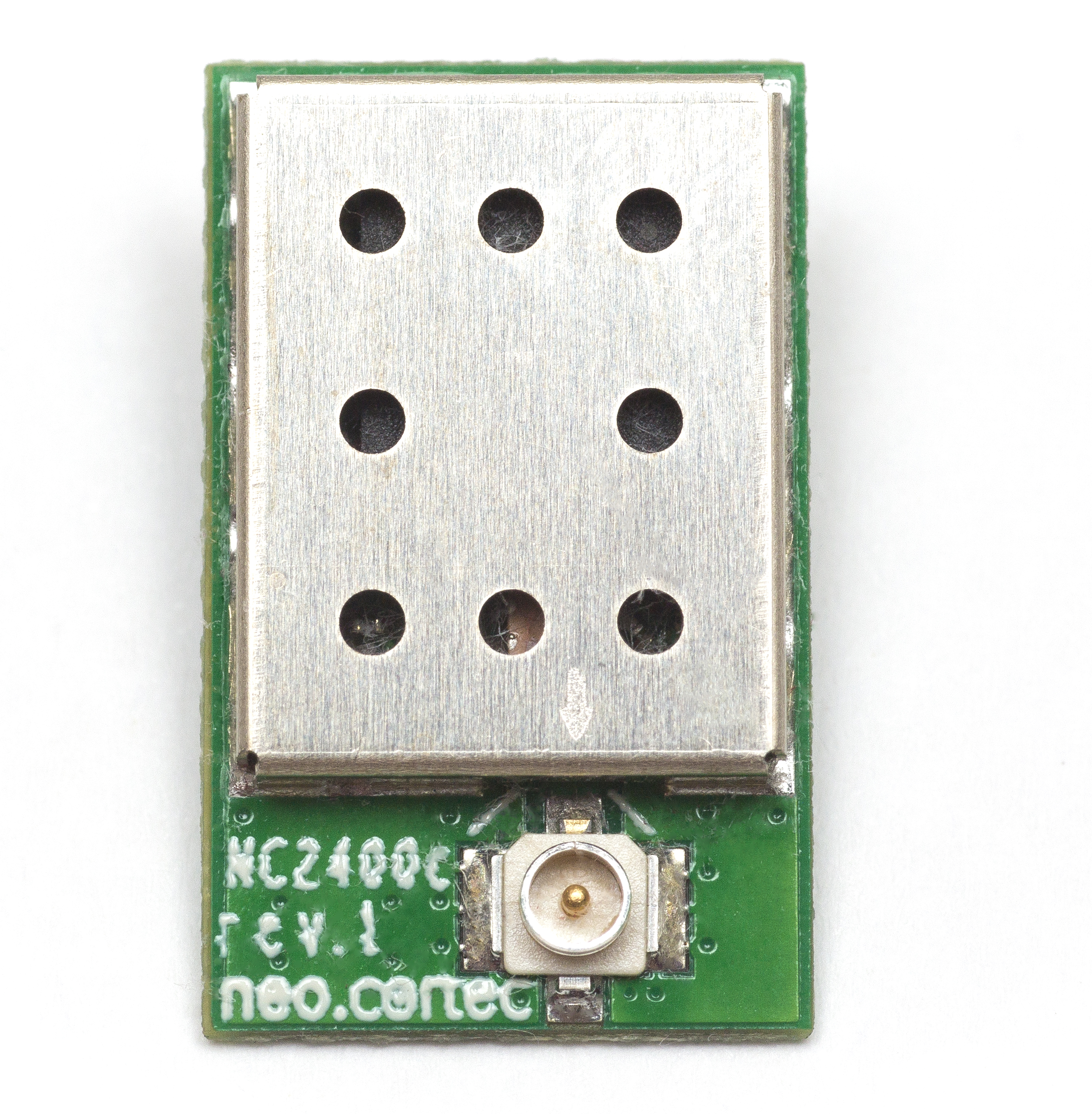
NCxxxx module:
The evaluation board is built around the NEOCORTEC NCxxxx. The module utilizes the NeoMesh technology to create a reliable, adaptive network with other devices in its vicinity. The module is available in several frequency bands. The currently available modules are:
 |
|
 |
|---|---|---|
| NC1000-8 | NC1000-9 | NC2400 |
| 868MHz SRD | 915MHz ISM | 2.4 GHz ISM |
IPX connector
Through the U.FL connector on the NeoCortec module, you can attach the whip antenna which comes prepackaged in your evaluation kit.
USB port
The evaluation board can be connected to your computer through a Micro USB port. Through this single physical interface, the Evaluation board provides two serial communications ports, which are used for each their own individual purpose:
| Application API | For sending and receiving payload data through the NEOCORTEC wireless network |
| System API | Used for configuration and debugging purposes |
Reset button
The reset button provides the opportunity to reset the NeoCortec module.
Battery clamp
The NeoCortec module can be used in battery operated mode. On the new module version, you can find a battery holder on the bottom side of the PCB. It can house two AAA batteries. The devices' low consumption allows for extremely long maintenance free operation on battery power.
Jumpers
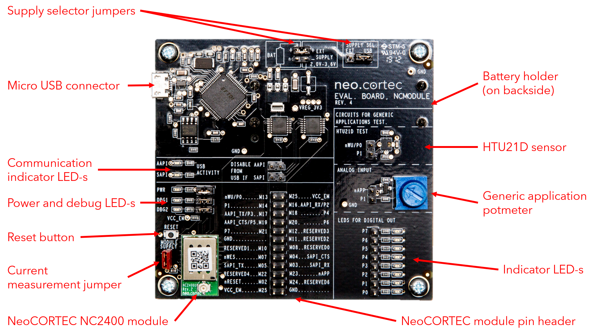
The evaluation board was designed to provide options for the testing of different functionalities. For this reason, several jumper pins are included, which can be used to connect or disconnect various hardware components.
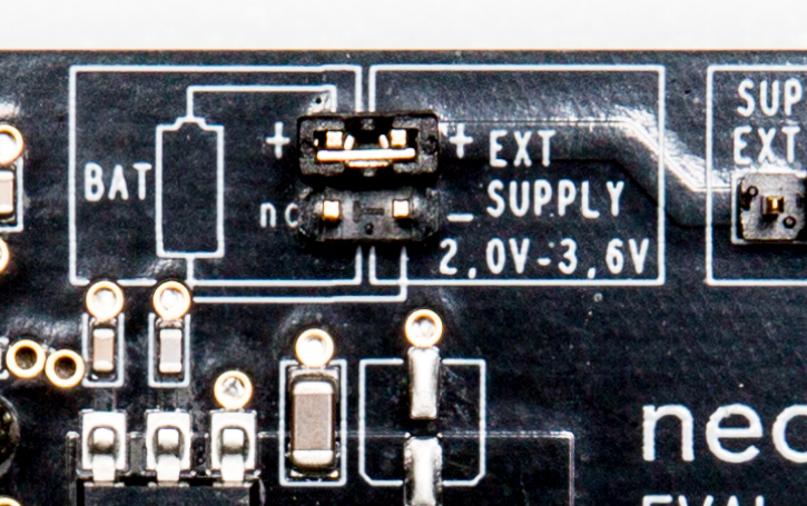
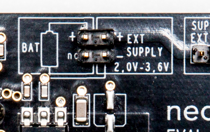
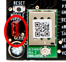
Battery/External supply Jumper
The Supply select jumper can be used to connect the battery clamp or some external supply to the Supply reg. select Jumper.
 |
 |
|---|---|
| Battery connection | Connect external supply |
The block diagram shows the connections between the jumper pins. For more information, please refer to the schematics diagram
of the Evaluation board Rev. 4.
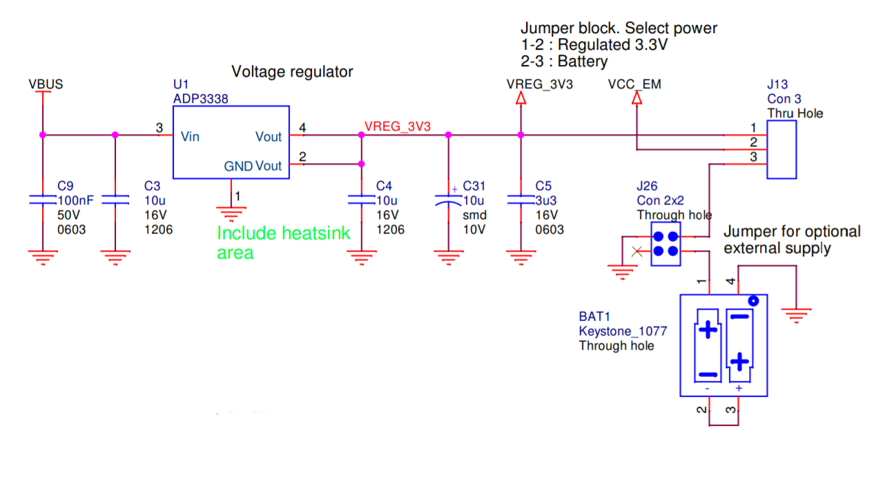
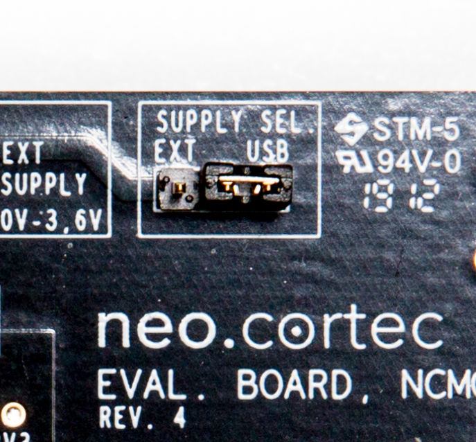
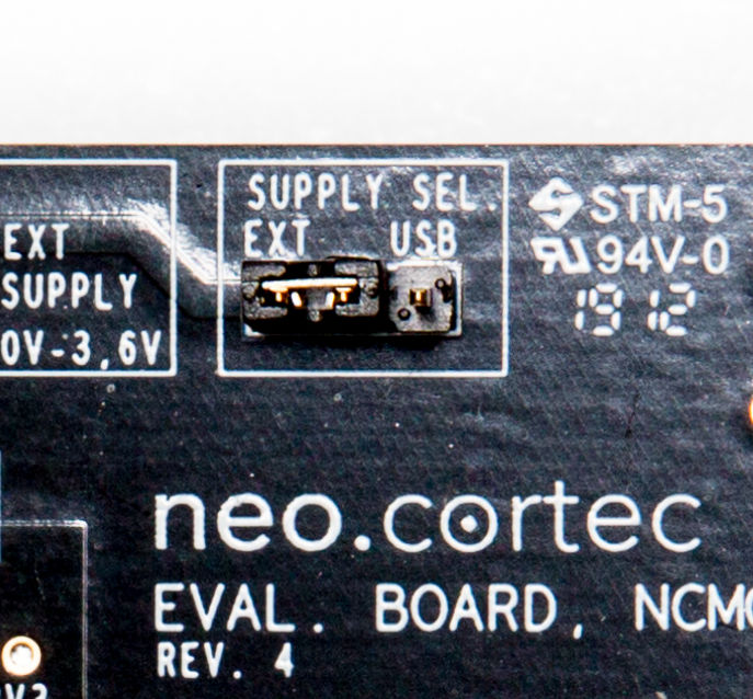
Supply reg. select jumper
The evaluation module can be supplied in four different ways. Through the USB port, using the pin header in the middle of the board, connecting an external source or through the battery clamp. In the case of supplying through USB, the Module supply: jumper shall be set to the USB option. If we provide current through the pin header in the middle of the board, the Module supply: select jumper is inconsequential. In the case of an external supply or battery operation, the jumper need to be set to "battery supply".
 |
 |
|---|---|
| USB | Battery supply |
Current supply jumper
The current supply jumper enables you to measure the individual consumption of the NEOCORTEC NCxxxx module independently from any of the other subsystems included on the evaluation board. For current consumption measurements, replace the jumper with a shunt resistor.
 |
|---|
| Current measurement connection |
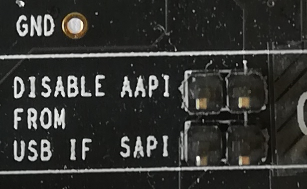
USB disable jumper
Attaching jumpers to the Disable from USB if: jumper positions, you can physically separate the UART, CTS and nWU lines coming from the USB connector. If you do not intend to attach a 3rd party controller to the evaluation board through the connector in the middle of the board, it is recommended to leave these jumpers void of any jumper sleeves. You can view the schematic design of the Evaluation board Rev. 4.
 |
|---|
| Both Application (AAPI) and System COM port (SAPI) enabled |
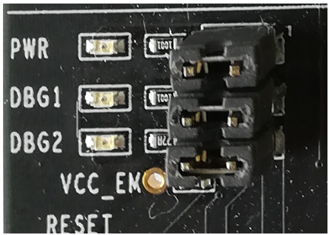
LED jumpers
There are three LED jumpers on the evaluation board. One for the power on LED, and two for two separate test LED-s. The LED-s are connected to the NEOCORTEC NCxxxx module and they are serving as debug-indicators.
 |
|---|
| All LEDs enabled |
Generic Application Tests
In the Rev. 4 evaluation hardware, the circuits for generic application tests are more separated/exposed on the PCB, compared to earlier revisions. In order to test the individual functionalities, please connect the appropriate segment of the PCB to the connector in the middle of the board. Every pin on the Generic Application Test side is labeled together with the pin on the middle connector it needs to be attached to. A small pouch of jumper wires is provided in the evaluation kit. (What is the generic application? )
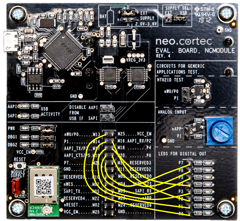
GPIO mode
The attached Jumper wires connect one digital output each to a LED. This way the changes on the output state can be easily observed.
 |
|---|
| Trimmer connected and ready to use |
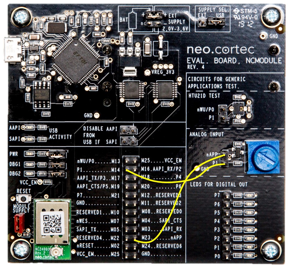
GPIO mode with ADC
The two jumper wires connected will enable the potentiometer supply voltage and attach the device to the one of the ADC-s input, providing a readily available analog signal source to be used with the generic application.
 |
|---|
| LEDs connected and ready to use |
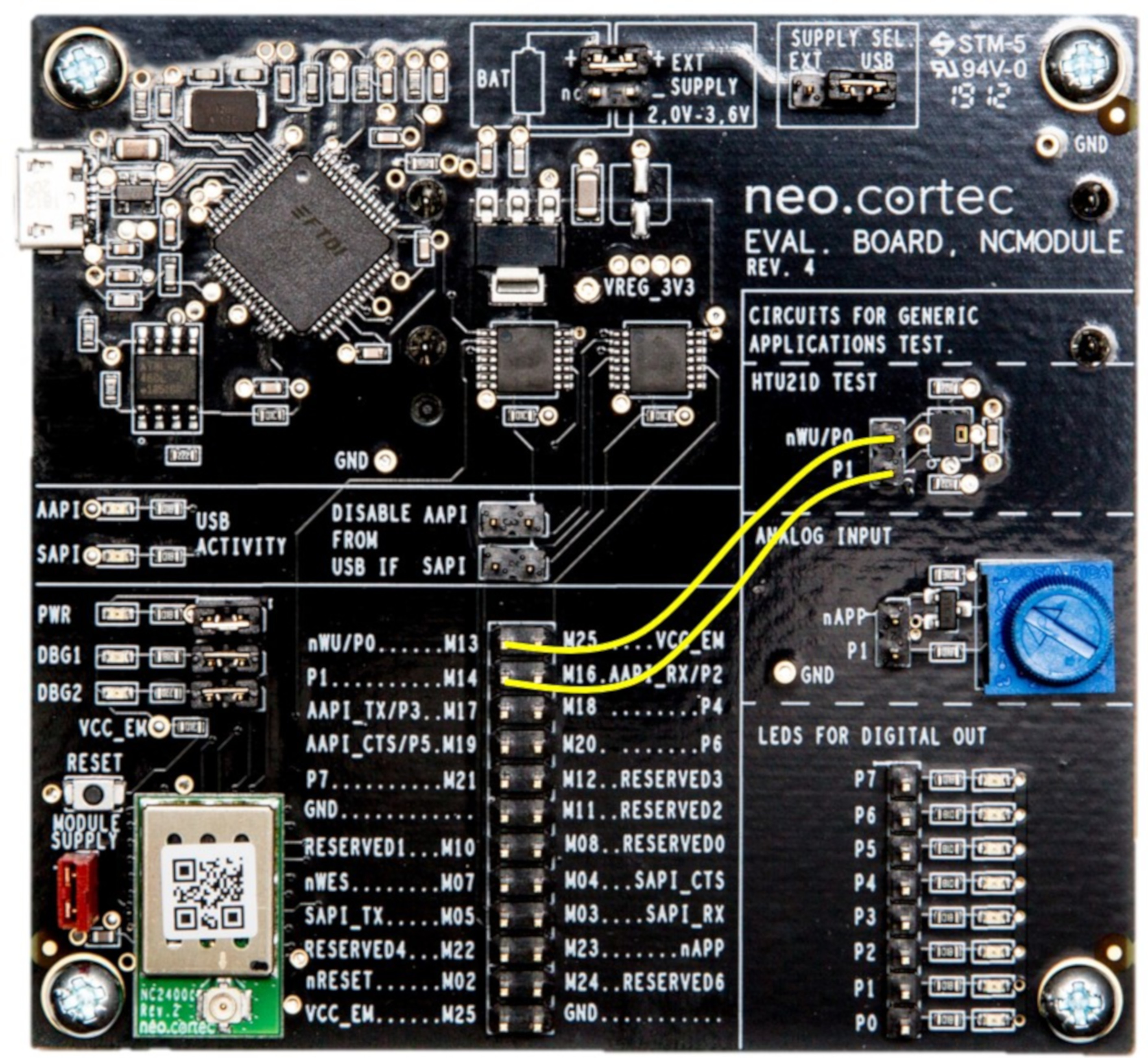
HTU21D mode
The attached jumper wires connect the HTU21D temperature-humidity sensor to the I2C bus on the NeoCortec module, enabling data transfer between the two devices.
 |
|---|
| I2C sensor connected |