Generic application
Description
The following tutorial lets you choose from the 4 different ways of setting up the generic application supplied with each NeoCortec module. You can find out more about the specific operation modes in the User Guide.
Generic application
You should think about the generic application as the program what controls the behavior of your NeoCortec node. The nodes cannot be programmed individually as a microcontroller, but the generic application offers a fairly broad level of control over the behavior of the device. Modifying the generic application settings enables you to use the module in several cases in a standalone fashion, without the need of an external microcontroller. Basic GPIO and analog signal acquisition capabilities are already built into your module, eliminating the need for an additional microcontroller in your product design. Configuring these functionalities correctly can shorten development time and decrease product complexity significantly.
Required hardware
- 2 NeoCortec Evaluation boards
- 2 USB cables
Required software
- NeoCortec Demo_App (Supplied on your USB card)
- NeoCortec Config_App (Supplied on your USB card)
Configuring for UART mode
Estimated time required: 5 minutes
As per default, your devices come reconfigured with the Generic application set to UART mode. This means that a microcontroller/computer can use the NeoCortec module's application UART interface to send messages through the NeoMesh network.
How to turn the UART mode on
If you need to set the generic application to UART mode, you can do so through the “Config App”.
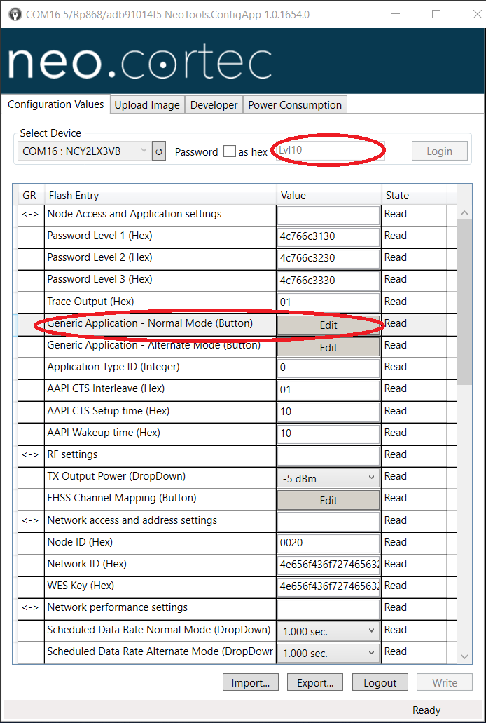
1. Open an instance of the config app, go to the “Configuration Values” tab and connect to the evaluation board you want to change.
In order to connect to the board you need to input the correct password. (Level 1 access is necessary to change the generic application settings.)
By default, this pass-phrase is "Lvl10". More about this in the User Guide.
2. Once logged in, find the “Generic application - Normal Mode (Button)” setting, and click on the “Edit” button in the same row.
 3. A window pops up with the possible settings for the generic application functionalities. Select “UART” in the Application type box. The correct setting shall look like this:
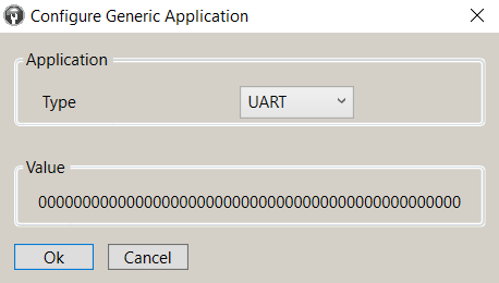 4. Hit “Ok”. Now the NeoCortec module can be used together with the message sending functionality of the “Demo App” again.
Do not forget writing the newly set values in the memory of the module using the "Write" button at the bottom right corner of the “Config App” window, as it was previously shown in the
General config settings tutorial.
Configuring for GPIO mode
If you want to use the generic application in GPIO mode, the relevant settings are available through the "config app".
- Open an instance of the "config app", go to the “Configuration Values” tab and connect to the evaluation board you want to change. In order to connect to the board you need to input the correct password. (Level 1 access is necessary to change the generic application settings.) By default, this pass-phrase is "Lvl10". More about this in the User Guide.
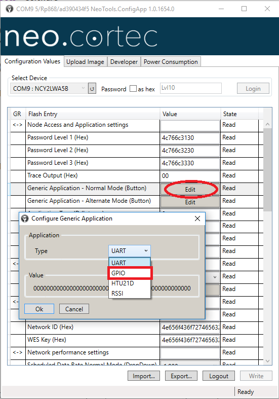
- Once logged in, find the “Generic application - Normal Mode (Button)” setting, and click on the “Edit” button in the same row.
- A window pops up with the possible settings for the generic application functionalities. Select “GPIO” in the Application type box.
-
After the following GPIO configuration window appears, you have the following options:
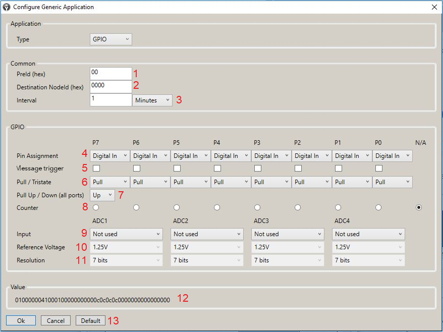
Designation Functionality 1 PreId - Arbitrarily chosen. Correct usage can help identify package formats. 2 Destination NodeId - The sink node which is the intended target of the generated message. 3 Interval - Time passed between subsequent generated packages. It is also the time elapsed between individual measurements, with the notable exception of the "counter" functionality. 4 Pin Assignment - Selects the functionality of the given pin on the module packaging. The options are: Digital In, Digital Out, Analog In. 5 Message trigger - If " Digital In " is selected in dropdown menu 4 above, then this checkbox decides, if a message should be sent upon detecting a falling edge (checked) or only at preset intervals (unchecked). 6 Pull/Tristate - Selects, if a digital input or output shall be pulled (Up/Down selected later), or Tri-State. 7 Pull Up/Down - Selects if the pins marked as " Pull " in dropdown menu 6 shall be pulled to Vdd or GND. 8 Counter - A single Digital In pin can be marked as counter (falling edge). This radio button sets which pin shall function as counter. 9 Input - The NeoCortec module has 4 built in ADC-s. If a pin in dropdown menu 4 is set as an Analog In, the same pin can be selected as the input for one of the ADC-s. The converters also can be set up to measure Vdd ( Vdd/3 ) or temperature through the internal temperature sensor. ( Temperatur Sensor ). 10 Reference Voltage - Configurable as: 1.25V , Vdd , External P7 or External P6-P7 . 11 Resolution - There are 4 available resolutions for the ADC-s. The measured value is stored on 2 bytes, arranged towards the MSB. 12 Value - The generated hex bitstring, to describe the previous settings. 13 Hitting the Ok button we can apply the changes. -
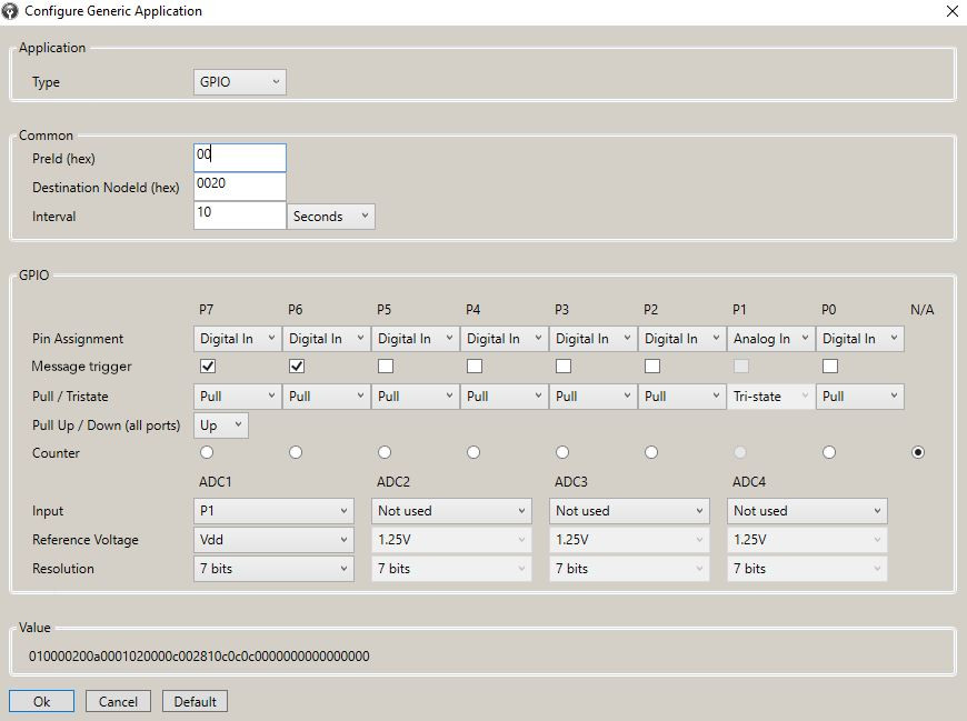
For the remainder of the tutorial, let us use the following settings:
- The receiving node of our tutorial setup is 0x0020, while the sender is 0x0040 .
- The interval between sent messages is decreased to 10 seconds.
- P6 and P7 are digital inputs, which trigger an instant message on a falling edge while P1 is marked as an analog input.
- ADC1 is linked to P1 with Vdd as reference voltage.
The finished setup shall look like this:
-
If we are satisfied with the settings, Hit the Ok button. When we arrive back to the "config app" "Configuration Values" tab do not forget to click the " Write " button and then log out.
“Ooops that didn’t work”
-
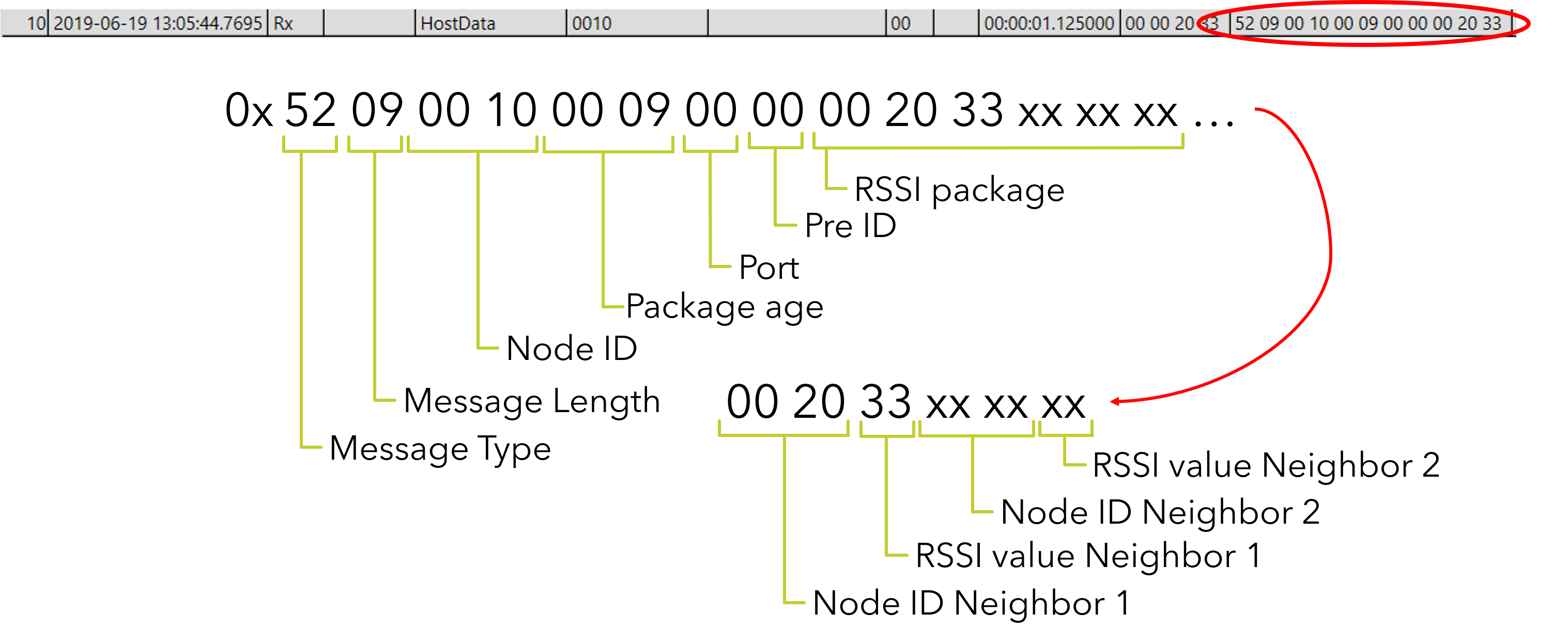
Now, start an instance of the "demo app", and connect to the 0x0020 module. After some time, the first package from the initiator node arrives. As it can be observed, subsequent packages have incrementing sequence numbers.
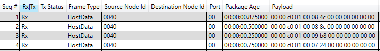
-
Please note, that the "config app" allows you to have two different modes configured for the generic application. One for " normal mode " and one for " alternate mode " . A typical setup can be GPIO functionality in " normal mode " operation and RSSI in " alternate mode ".
-
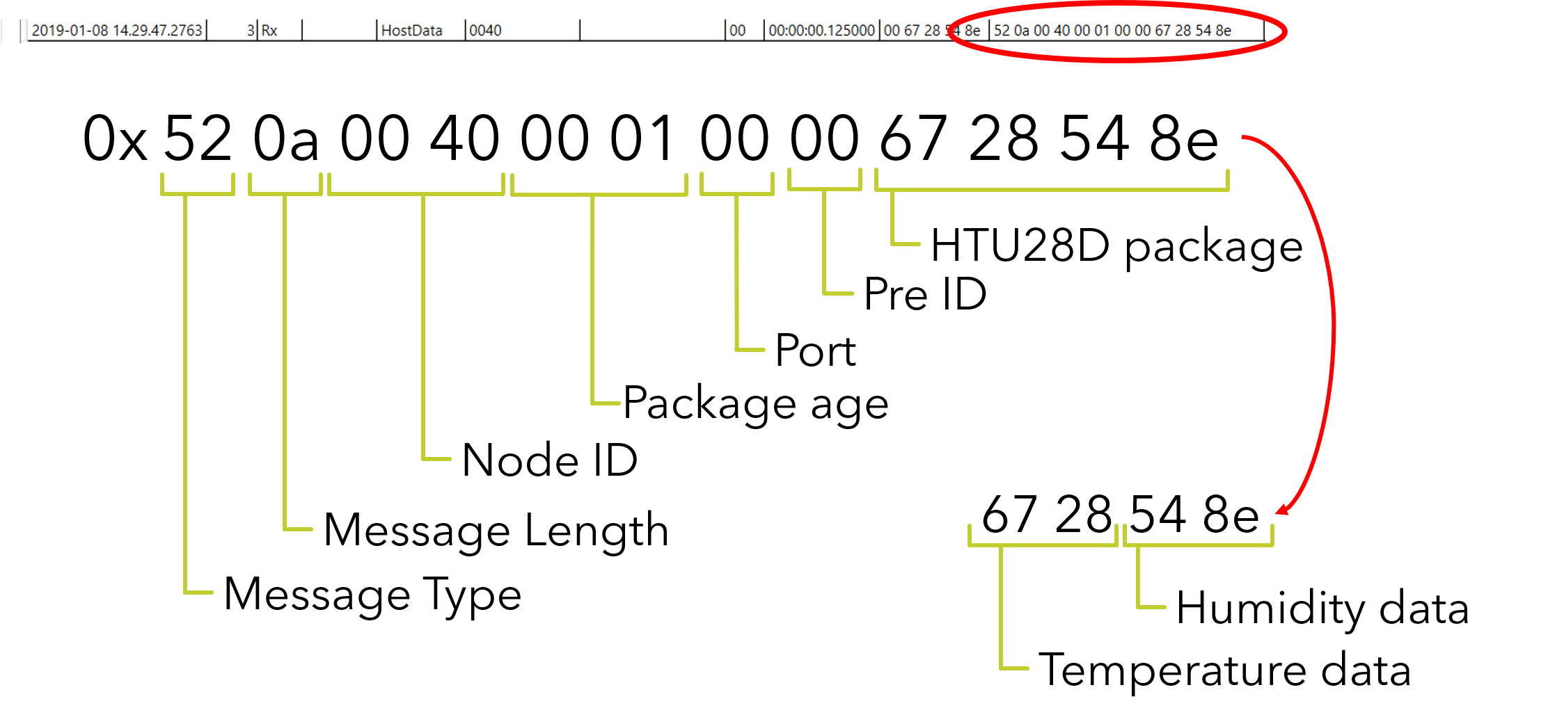
The message format can be interpreted the following way.
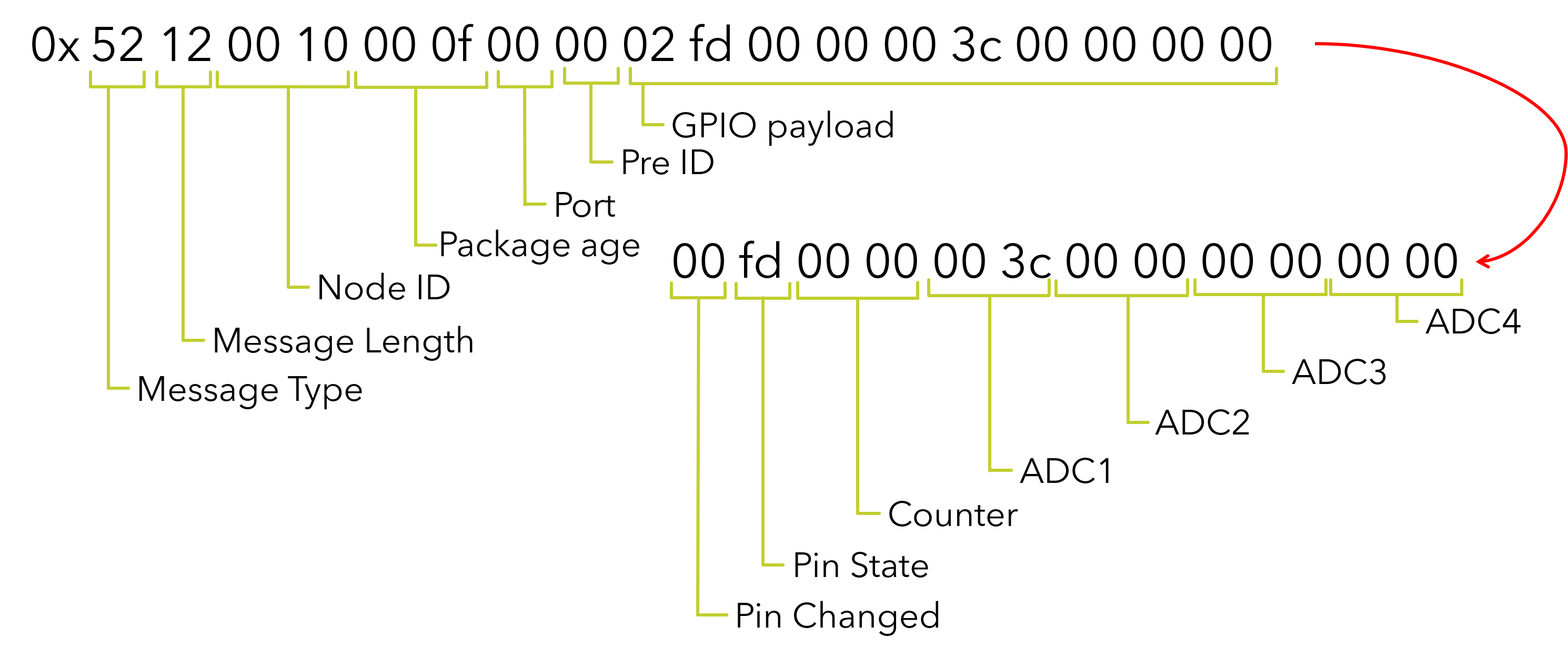 More about the generic application and the GPIO-setup can be found in the User Guide.
Configuring for HTU21D
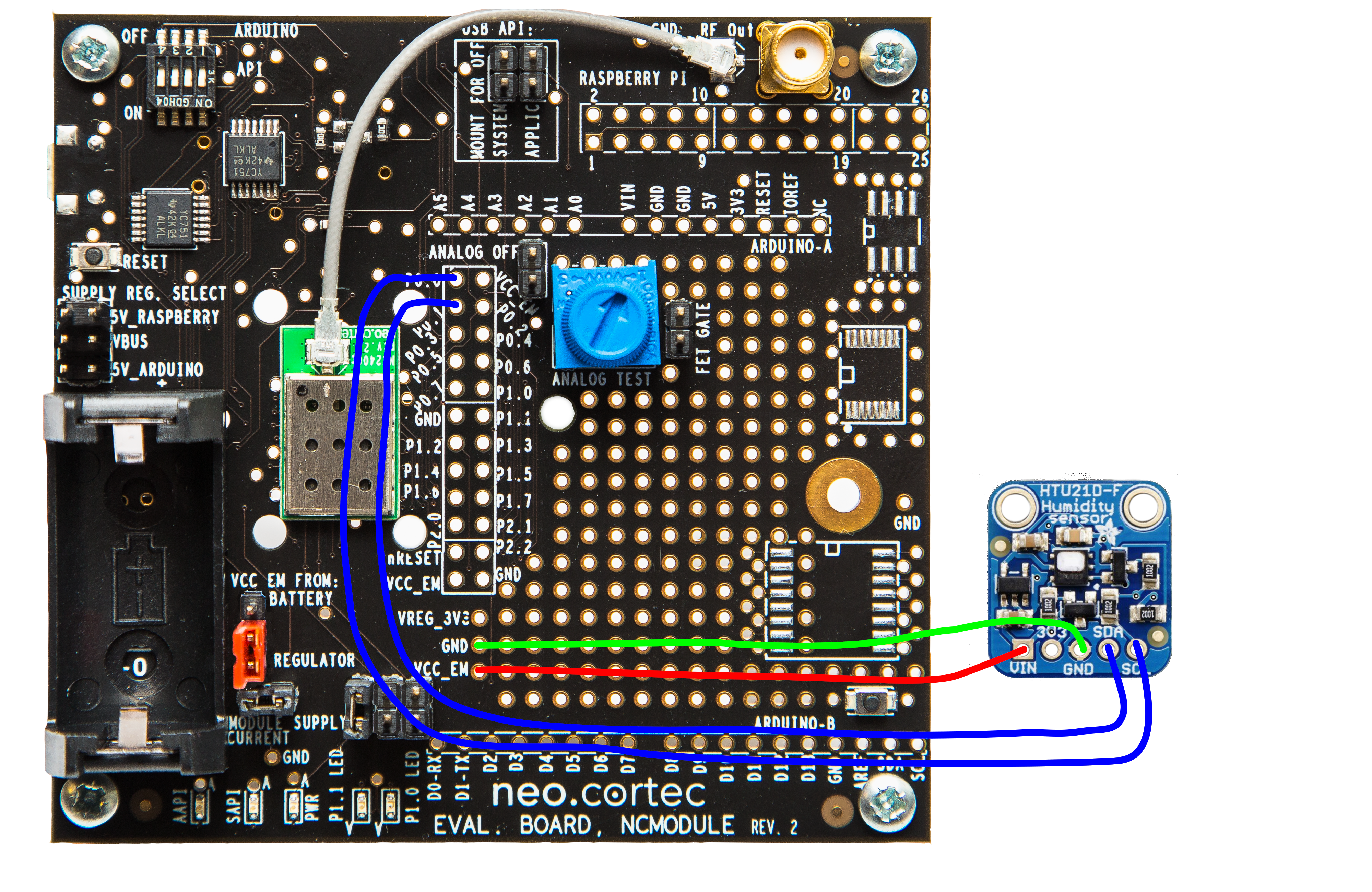
HTU21D is a temperture-humidity sensor with an I2C interface. The NeoCortec moduels come with a preconfigured generic application profile enabling the user to connect to this specific IC through an I2C interface. Neither the IC type, nor the pin layout chan be changed for this application profile. For the physical layout of the setup, please refer to the HTU21D reference design schematics. A simplified wiring diagram can be seen below:
 |
 |
|---|---|
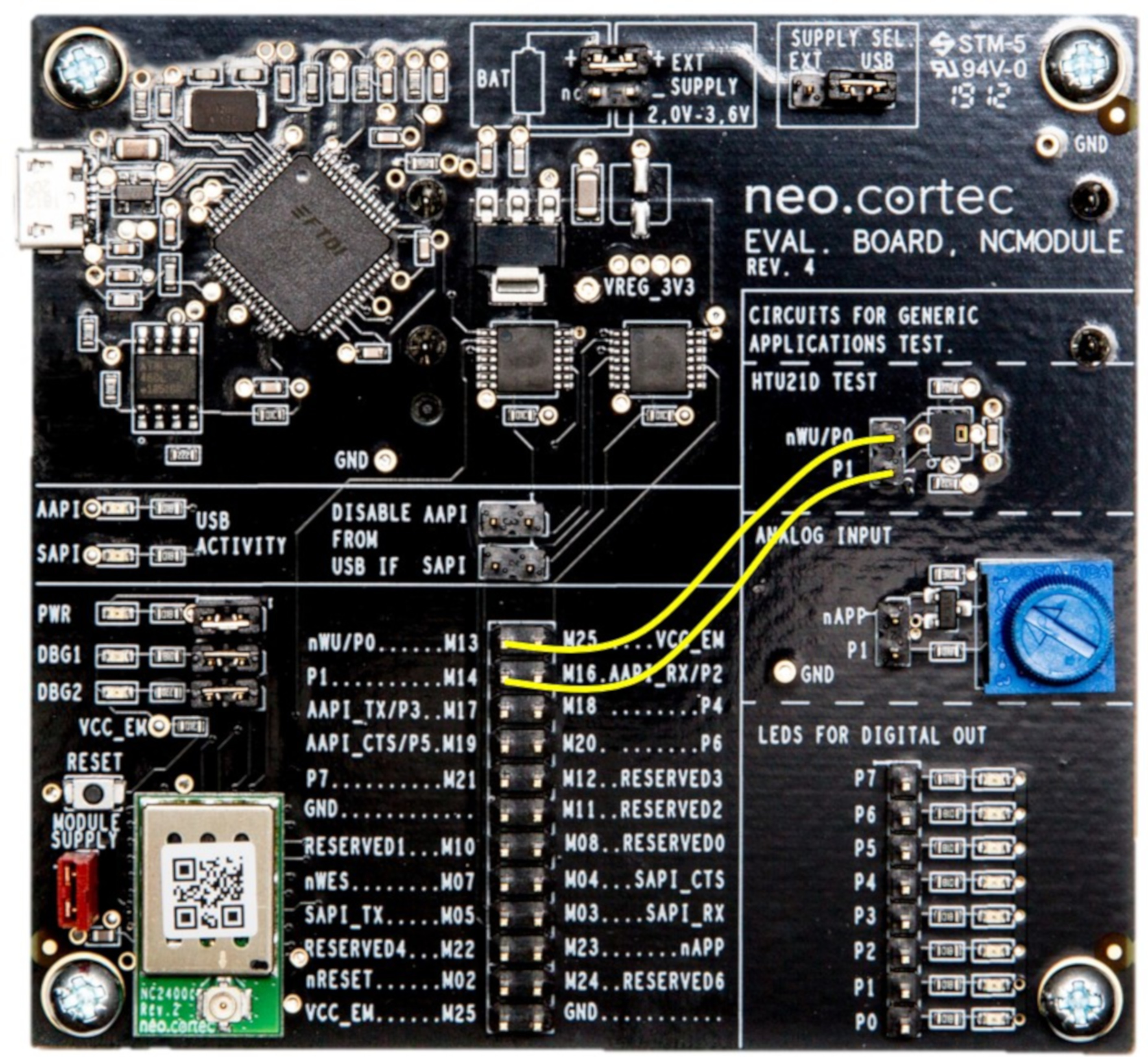
| Rev. 2 Demo board wiring diagram (Soldering required) | Rev. 4 demo board wiring diagram (Jumper wires required) |
Once you applied the HUT21D breakout board to your evaluation board, teh result should look something like this.
In the following tutorial we will set up the normal mode operation of the generic application to support the HTU21D breakout board. More information on the board can be found here.
- Open an instance of the "config app", go to the “Configuration Values” tab and connect to the evaluation board you want to change. In order to connect to the board you need to input the correct password. (Level 1 access is necessary to change the generic application settings.) By default, this pass-phrase is "Lvl10". More about this in the User Guide.
- Once logged in, find the “Generic application - Normal Mode (Button)” setting, and click on the “Edit” button in the same row.
-
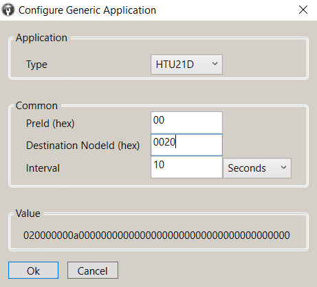
On the popup window, select the HUT21D option in the dropdown menu. This action changes the window's appearance. Changes to the following settings are needed:
- The receiving node of our tutorial setup is 0x0020, while the sender is 0x0040 .
- The interval between sent messages is decreased to 10 seconds.
-
If we are satisfied with the settings, Hit the Ok button. When we arrive back to the "config app" "Configuration Values" tab do not forget to click the " Write " button and then log out.
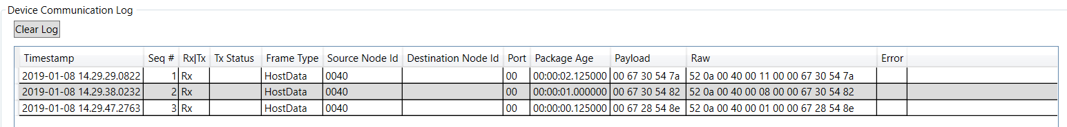
- Now, start an instance of the "demo app", and connect to the 0x0020 module. After some time, the first package from the initiator node arrives. As it can be observed, subsequent packages have incrementing sequence numbers.
-
The encoded message payload from the sensor can be interpreted using the two equation below. These formulas and more useful information on the decoding and buildup of the HUT21D message can be found in the user guide, and the sensors datasheet.

-
More I2C based sensors are also supported by the NeoCortec module. For a full, up to date list contact NeoCortec..
Configuring for RSSI mode
If you want to use the generic application in RSSI mode, the relevant settings are available through the "config app". In RSSI mode, the sender node will pass it's neighbour list and the respective RSSI values. This setting is useful as an alternate mode generic application setup, as it helps the network-owner have a better picture of the network's physical layout. For the purposes of this tutorial we will set up the Generic application for RSSI as the normal mode operation.
- Open an instance of the "config app", go to the “Configuration Values” tab and connect to the evaluation board you want to change. In order to connect to the board you need to input the correct password. (Level 1 access is necessary to change the generic application settings.) By default, this pass-phrase is "Lvl10". More about this in the User Guide.
- Once logged in, find the “Generic application - Normal Mode (Button)” setting, and click on the “Edit” button in the same row.
-
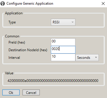
On the popup window, select the RSSI option in the dropdown menu. This action changes the window's appearance. Changes to the following settings are needed:
- The receiving node of our tutorial setup is 0x0020, while the sender is 0x0040 .
- The interval between sent messages is decreased to 10 seconds.
Once finished with the setup, the window shall look like this:
 4. If we are satisfied with the settings, Hit the Ok button. When we arrive back to the "config app" "Configuration Values" tab do not forget to click the " Write " button and then log out.
“Ooops that didn’t work” 5. Now, start an instance of the "demo app", and connect to the 0x0020 module. After some time, the first package from the initiator node arrives.